Access control
.jpg)
Access control setup example
- Setup user access using electronic keys and provide a web interface for user management.
- Control door access using a magnetic lock, bolt lock, electric latch, or other.
- Use push/exit button for controlling door exit access.
- Use emergency (system-independent) push/exit button for controlling door exit access in case of emergency.
- Setup sound and light alarm beacon in case of an alarm.
- During non-working hours: in case of movement, breakage/vibration of the door/windows, or door opening without permission, start sending the video stream to an FTP server and SMS and E-mail notifications
Installation
Such a scenario can be accomplished using 'VT335 S / Monitoring unit' or other. The diagram below shows the connections.
.jpg)
1. Install "VT10 / 1-Wire module". Connect VT107 / RFID reader to 1-Wire port.
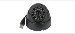
2. Connect "USB100 / USB camera" camera to a USB port.
3. Optionally connect up to 4 IP cameras.
4. Connect VT570 / PIR sensor to one of the analog ports.
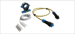
5. Connect "VT540 / Vibration sensors" and "VT530 / Access sensors" to analog ports of the monitoring system. These sensors are chainable and can be connected to each other. All sensors in one chain connection are seen by the system as one sensor.
6. Install push/exit button to dry contact inputs of the unit. nstallation instructions.
7. Connect bolt lock or magnetic lock or electric latch to the "12V 0.25A" relay of the monitoring system. Read more: Connecting 12V devices to 12V outputs. In case the device requires a different voltage or amperage, "VT11 / Dry contact out" can be used.
8. Connect "VT103 / Alarm beacon" or "VT105 / Strobe light" or a light tower to 12V 0.25A relay.
9. Connect emergency (system- independent) push/exit button for controlling door exit access in case of emergency.
Configuration examples
All configurations are made from within the web interface of the system. Default IP is 192.168.0.193. Default password: guest. Default login: guest.
Add user's electronic keys
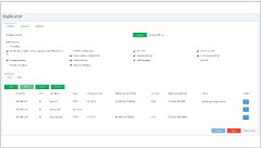
VT107 / RFID reader is detected by the system automatically. The system will add "Access control" panel to the interface. Inside the "Access control" panel You can now add RFID cards and apply the user's name to each such electronic key.
.jpg)
Relay configuration (Lock control and alarm beacon)
In the "System tree" menu of the web interface under the "Power 12V 0.25A" section find the relay we are connecting the device to. By default Power-1 and Power-2. Rename it, set initial state, and set Pulse duration time in seconds to 5s. for example.
%20configuration%20(Access%20control%20Vutlan).jpg)
Dry contact inputs configuration (Exit button and window/door sensors)
In the menu "Dry contacts" edit the dry contact input the Exit button is connected to. Rename it, choose the type (changes the icon), choose the current state.
%20(Access%20control%20Vutlan).jpg)
Configure sensors (vibration, temperature, access, motion)
In the "System tree" menu of the web interface find and configure the sensors. Edit name, adjust thresholds: low warning, warning, normal, high warning, and high alarm.
%20(Access%20control%20Vutlan).jpg)
Configure notifications
In the web-interface menu "System tree" press "+". Now You can add E-mail notifications, SNMP trap, SMS notification, Web SMS notification, SMS Gate service, SNMP Get, and others.
.jpg)
Setup logic: RFID reader and relays
If "iButton" is normal (reads correct reading), then "Power-1" (lock) pulse. Previously we have setup the pulse to 5 seconds.
.jpg)
Setup logic: Alarm notifications
If "iButton" is normal (reads correct reading), then "Power-1" (lock) pulse. Previously we have setup the pulse to 5 seconds.
.jpg)
